
Support
Technical Help
| More Detailed Motor Help on: | ||||||||||||||||||||||||||||||||||||||||||||||||||||||||||||||||||||||||||||||||||||||||||||||||||||||||||||||||||||||||||||||||||||||||||||||
|
General FAQ
Q—How is torque measured on the small gear motors? A—The simplest and most direct method is to secure a pulley to the output shaft which winds up a cord with a weight attached. The torque developed is the product of the weight and radius of the pulley and is usually expressed in ounce-inches. Q—How is torque measured on the motors without gear units? A—Due to the higher shaft speeds, the weight and pulley method is impractical and either a version of the prony brake or a dynamometer must be used to measure torque. Q—What do the terms pull-in, pull-out, full-load, break-down, and locked-rotor mean in regard to torque? A—Pull-in torque is the maximum torque at which a synchronous motor can accelerate its load to synchronous speed. Pull-out torque is the maximum torque which a synchronous motor can develop and still maintain synchronous speed. Full-load torque is the torque developed by a non-synchronous motor at its rated full-load speed. Break-down torque is the maximum torque that the motor can develop. With a synchronous motor this will be at a speed slower than synchronous speed and with a non-synchronous motor it will be at a speed slower than full-load speed. Locked-rotor or starting torque is the torque developed with the rotor at standstill. Q—How do variations in voltage affect motor torque? A—Torque will vary with changes in voltage. Torque ratings are given at rated voltage. Q—What is the difference between motor torque ratings and the gearing torque ratings? A—The motor torque rating is the torque that the motor can produce at the output shaft of a particular gear reduction. At very high reductions (low output speeds) the output torque can reach very high values exceeding the strength of the gearing. For this reason a maximum torque value (gear torque rating) must be specified to prevent gearing damage. Q—How do various types of loads affect the gear torque rating? A—Gear torque ratings are based upon a uniform steady torque load. Dynamic or shock loads impose stresses which can exceed gearing strength or cause early fatigue failure. To a certain extent this can be compensated by reducing the gear torque rating (see Service Factor Table). However, dynamic braking with inertial loads or locking of the output shaft can force the gearing to absorb destructive amounts of kinetic energy stored in the momentum of the load or the rotor with immediate or rapid failure. Q—What is meant by the temperature rise of a motor and how does it apply? A—It is the difference between the measured temperature of the motor winding and the temperature of the air surrounding the motor. Electrical insulation systems are limited in the degree of temperature that they can withstand. Standard motors have Class A insulation systems which are rated at 105˚C for the hottest-spot temperature. A hot-spot allowance must be made for the difference between the measured temperature of the winding and the actual temperature of the hottest-spot within the winding, usually 5˚ to 15˚C depending upon the type of motor construction. The sum of the temperature rise, the hot-spot allowance, and the temperature of the ambient must not exceed the temperature rating of the insulation. Q—What is the minimum operating temperature of a standard motor? A—When a motor is started the operating temperature will be the same as the ambient temperature. Frictional losses in the bearings and gearing increase as the temperature of the lubricants decreases due to the change in lubricant viscosity. This change is progressive although not uniform) over the entire temperature range so that there is no fixed point of demarcation. Practically, when the torque of the motor has been reduced by frictional losses to equal that required by the load, the minimum temperature has been reached. Q—What does “Impedance Protected” mean? A—Many motors in the subfractional horsepower sizes can be designed with enough impedance (opposition to A.C. current) in the windings to limit the locked rotor currents to values that do not cause the motor to overheat beyond a safe temperature. Q—Can motors designed for 60 Hz. be operated on 50 Hz? A—Not without changes in performance. Some types are extremely sensitive to frequency change and the factory should be consulted before 50/60 Hz. operation is planned. Q—Can the synchronous motors be operated with a variable frequency to provide speed control? A—Yes, but with certain power supply requirements and only over a limited range. The factory should be consulted for recommendations. Q—Are there other methods of obtaining variable output speeds? A—Where continuously variable non-synchronous speed is required, the induction and D.C. motor should be considered. Certain applications might be adaptable to the use of stepper motors as well. Q—What are the characteristics of the hysteresis synchronous motors? A—One of the outstanding features is its ability to accelerate high inertia loads to synchronous speed. Operation is smooth and quiet and, in the external rotor designs, the “flywheel effect” provides very uniform angular velocity. Q—How can the speed of a synchronous motor be checked to verify synchronous operation under load? A—Observation of the rotor under a stroboscopic light source synchronized with the supply voltage will show a stationary pattern if the rotor is running at sync speed. A continuously moving pattern indicates that the rotor is “slipping sync,” probably from loading in excess of pull-out torque capability. An oscillating pattern indicated a variation torque angle (discussed earlier) caused by a varying load or voltage. Q—What is the reluctance synchronous motor? A—Basically it is a synchronous version of the more common induction motor. Synchronous operation is attained by salient poles produced by flats or notches on the rotor. Size and cost are generally lower than a hysteresis motor of comparable power, however they have limited ability to accelerate inertial loads and have more inherent vibration due to the salient poles. Q—Where do permanent magnet synchronous motors fit in? A—Recent developments in magnet materials have raised this type of motor to new levels of efficiency featuring high torque to size ratio and moderate cost. Additional features are: inherent dynamic braking, impedance overload protection and low rotor speed for quiet operation and rapid acceleration. The motor’s limited ability to start and synchronize inertial loads and its sensitivity to parameters of voltage and phasing capacitance should be noted in application. With a modification of the winding and the proper electronic drive circuitry this motor type will operate as an excellent stepper motor. Q—How does the high-slip motor differ from the normal-slip? A—The high-slip motor has a higher resistance rotor which provides higher starting torque and slower full-load speed. In addition the shape of the speed vs. torque curve is much more linear which gives wider range and more stable operation where speed control is applied. Q—What is a stepper motor? A—A stepper motor could be defined as a brushless D.C. motor with a fixed number of steps or stable positions per revolution when driven by sequential excitation of its windings. There are several types of steppers available with the permanent magnet rotor stepper being one of the most widely used. Performance depends to a great extent upon proper selection and matching of the electronic driver. Steppers can produce an error free ratio of rotational position to signal pulses up to a maximum speed with the ability to start, stop or reverse direction. Beyond this point (known as the slew range) the motor cannot be started, stopped or reversed and still maintain pulse and step integrity. PM steppers provide inherent detent torque when not energized; an asset in many applications. Q—What is a permanent magnet D.C. motor? A—These motors use permanent magnets to provide field flux instead of wound field coils. Reliability is improved, efficiency is higher and the speed-torque curve is linear. Due to the absence of the wound field, however, field control is not possible with this type. Q—How do the HURST® PC and AR clutch motors differ? A—Both models utilize an electrically actuated mechanical clutch but of different design. The PC clutch couples and uncouples the motor from the gear train with a braking action upon the gearing and output shaft when the motor is disengaged. The AR clutch operates directly upon the output shaft. When disengaged, the output shaft is free to turn in either direction with minimal resistance. Torque Definitions Torque is the product of a force and the radius at which it is applied. The British unit of torque is pound-feet and in smaller motors this unit is reduced to ounce-inches. The metric unit of torque is Newton-meter. Few motors produce a single value of torque over their entire speed range so that a torque vs. speed curve is often necessary for torque evaluation. Definitions of terms used to describe specific points on the curve are listed below along with definitions of some other commonly used terms for motor torque specification. Pull-In Torque: the maximum torque at which a synchronous motor (stepping motor included) can accelerate its load to synchronous speed. Pull-Out Torque: the maximum torque which a synchronous motor (stepping motor included) can develop and still maintain synchronous speed. Full-Load Torque (Rated Torque): the torque developed by a non-synchronous motor at its rated full-load speed. Breakdown Torque: the maximum torque that the motor can develop; it occurs as a point on the speed-torque curve below synchronous or full-load speed. Locked-Rotor Torque: the torque developed with the rotor at standstill. Holding or Static Torque (Stepping Motor): the torque required to displace the rotor from its equilibrium position with one or more stator phases energized with the rotor at rest. Detent or Residual Torque (Permanent Magnet Motor): the torque developed in an unenergized motor when the permanent magnet rotor is displaced from a position of minimum stator reluctance. Variable Frequency Operation of AC Motors Sometimes a single motor is specified for both 50 and 60 Hz operation. Since inductive reactance and capacitive reactance vary dissimilarly with frequency, optimum performance must usually be compromised when a single winding/capacitor combination is operated at different frequencies. Some types of motors are more sensitive than others to frequency changes. As a general rule synchronous motors and especially permanent magnet motors are more sensitive than induction motors. The factory should be consulted before 50/60 Hz operation of a motor is planned. Operation over a wider frequency range is extremely difficult to accomplish with capacitor phased motors and is not recommended. Reliable operation requires a two phase power supply with applied voltage as a function of frequency. Gearing If gear units had no losses, the torque at the output shaft of a gear motor would equal the motor torque multiplied by the reduction of the gear train. Since all gearing does have some internal losses, the actual output torque will be less than the calculated no-loss value by a factor known as gearing efficiency. The efficiency of a gear train will vary with the number of gears. For rough approximation, a value of 7% to 10% loss per gear may be assumed. When precise calculation is necessary for a specific gear reduction, values should be obtained from the factory. When high gear reductions are used, the torque at the output shaft may exceed the strength of the gearing. For this reason a maximum torque value, a gear torque rating, must be specified to prevent gearing damage. Gear torque ratings are based upon a uniform, steady torque load. Dynamic or shock loads impose stresses which can exceed gearing strength or cause early fatigue failure. To some extent this can be taken into consideration in a reduced gear torque rating. However, dynamic braking with inertial loads or locking of the output shaft can force the gearing to absorb destructive amounts of kinetic energy stored in the momentum of the load or the rotor with immediate or rapid failure. As an example, permanent magnet motors with gear trains should not be stalled since the inherent pulsating nature of the stall torque can cause gearing damage in a short period of time. Service Factors for Gear Motors
To obtain the service torque rating of the geared motor, the rated output torque must be divided by the applicable
service factor. Note: Certain applications may impose dynamic stressed beyond the scope of the classifications
given.
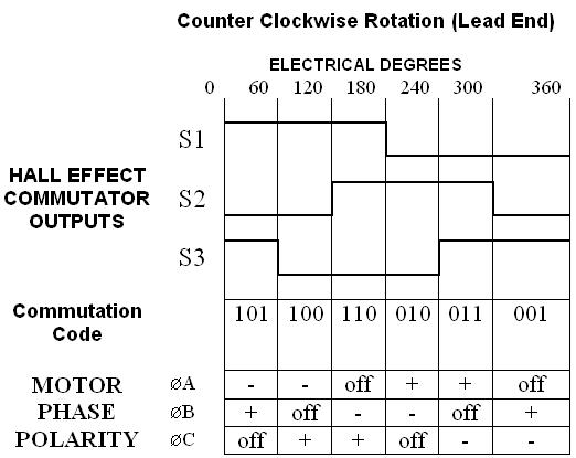
Temperature and Insulation Systems Temperature has an effect upon electrical resistance, magnetic characteristics, viscosity of lubricants, rate of volatilization of lubricants, dielectric strength of insulation and life of physical components in general. These effects must be taken into consideration in each motor application. The temperature rise of a motor is the difference between the measured temperature of the motor winding and the ambient temperature. Electrical insulation systems are classified according to the maximum temperature that they can withstand. HURST® motors have either Class A or Class B insulation systems which are rated at 105° C and 130° C respectively for the hottest-spot temperature. A hot-spot allowance must be made for the difference between the measured temperature of the winding and the actual temperature of the hottest spot within the winding, usually 50° C to 150° C depending upon the type of motor construction. The sum of the temperature rise, the hot-spot allowance, and the temperature of the ambient must not exceed the temperature rating of the insulation. The temperature rise of a motor should also be specified at a particular operating point, e.g., no-load, full-load, or locked-rotor. Many of the HURST® motors are "impedance protected," that is, they are designed with enough impedance in the windings to limit the locked rotor currents to values that do not cause the motor to overheat beyond a safe temperature. Other motors are available with a thermal protector, a device installed adjacent to the stator winding which will disconnect the motor from the line should the winding temperature increase beyond a safe value. The life of the electrical insulation and of the lubricants are adversely affected by high temperatures. A generally accepted "rule of thumb" is that for every 10° C increase in operating temperature, life is halved. Other Definitions Ambient Temperature - The temperature of the surrounding environment. BLDC (Brushless DC)/Brushless Permanent Magnet (BPM) Motor - A synchronous electric motor which is powered by direct current (DC) electricity and which has an electronically controlled commutation system, instead of a mechanical commutation system based on brushes. In such motors, current and torque, and voltage and rpm are linearly related. Commutation - The action of applying currents or voltages to the proper electrical motor phases as to produce optimum motor torque at a motor's shaft. Duty Cycle – The relationship between the on-time and off-time of a device. Encoder - An electro-mechanical device used to convert the angular position of a shaft or axle to an analog or digital code. See also Resolver. HST23 - HURST® Segmented Technology NEMA 23 (2.3 inch frame) NEMA (National Electrical Manufacturers Association) – Sets many common standards used in electrical products. Planetary Gear Train - An assembly of meshed gears consisting of a central gear, a coaxial internal or ring gear, and one or more intermediate pinions supported on a revolving carrier. PPR - Pulses per Revolution PWM (Pulse Width Modulation) – A type of signal that varies the duty cycle, to either convey information over a communications channel or control the amount of power sent to a load; uses a square wave where the width of its pulse is varied periodically, resulting in the variation of the average value of the waveform. Resolver - A type of rotary electrical transformer used for measuring degrees of rotation. It is considered an analog device, and has a digital counterpart, the encoder. Spur Gear - A toothed wheel with radial teeth parallel to the axis. Tachometer - An instrument or circuit that measures the rotation speed of a shaft or disk. TTL (Transistor-Transistor Logic) - A class of digital circuits built from bipolar junction transistors (BJT), and resistors. It is called transistor–transistor logic because both the logic gating function (e.g., AND, NOR) and the amplifying function are performed by transistors. Brushless DC Permanent Magnet Motors Brushless Motor Construction DC brushless motors are similar in performance and application to brush-type DC motors. Both have a speed vs. torque curve which is linear or nearly linear. The motors differ, however, in construction and method of commutation. A brush-type permanent magnet DC motor usually consists of an outer permanent magnet field and an inner rotating armature. A mechanical arrangement of commutator bars and brushes switches the current in the armature windings to maintain rotation. A DC brushless motor has a wound stator, a permanent magnet rotor assembly, and internal or external devices to sense rotor position. The sensing devices provide signals for electronically switching (commutating) the stator windings in the proper sequence to maintain rotation of the magnet assembly. The rotor assembly may be internal or external to the stator in a DC brushless motor. The combination of an inner permanent magnet rotor and outer windings offers the advantages of lower rotor inertia and more efficient heat dissipation than DC brush-type construction. The elimination of brushes reduces maintenance, increases life and reliability, and reduces noise and EMI generation. Brushless Motor Commutation The possible number of phases and winding arrangements for the DC brushless stator are quite varied. As in the case of brush-type DC motors, increasing the number of phases reduces torque ripple. However, an important practical consideration for DC brushless motors is the number of electronic switches required to commutate the phases. Three phase motors provide a compromise in this regard and are popular in many applications. The winding arrangement for a three phase motor may be either a Y or a Δ configuration. The most efficient operation of the motor requires current flow in more than one phase at any instant and current reversal in each of the phases at some point during 360 electrical degrees of rotation. This in turn requires a minimum of two electronic switches per phase. It may be noted that the Y configuration with a lead common to the three phases can be commutated in a unipolar mode with only three electronic switches. However, the motor torque is reduced with this scheme. Hall Effect Commutation Rotor position sensing is essential for proper commutation of DC brushless motors. Magnetic sensing with inexpensive Hall effect switches is frequently adequate. The devices require little space and can easily be placed within the motor. Optical encoders or resolvers may also be used. Cost, operating environment of the motor, intended application and performance all influence the choice. As an example of Hall effect commutation, consider the typical commutation scheme shown in the table for the HURST® motors. Commutation of a three phase motor with current reversal requires that the windings be switched every 60 electrical degrees. If three sensing devices are spaced 120 electrical degrees apart, and if each device has a 50% duty cycle, six discrete 3-bit signal states are produced at 60 degree intervals as the rotor turns. Each change of state triggers switching of the stator windings to a particular terminal pair and polarity. Reversing The sensors are located so that switching occurs 30 electrical degrees before the peak in the torque vs. angle curve for that terminal pair. Operation of the motor in the reverse direction requires only a change in the switching sequence. A number of manufacturers offer an integrated circuit to perform the sensor signal decoding and provide signals to sequence the power switches for the motor phases. Brushless Motor Control DC brushless motors are used in the same types of applications as DC brush-type motors, e.g., servo, constant speed, variable speed, controlled torque, etc. The methods of control are similar to those for brush-type motors. Most will involve some type of current control whether in an open loop mode or a closed loop mode or a closed loop mode with position and perhaps velocity sensing. A description of a typical drive circuit will illustrate the possibilities. The power switches for a three phase motor are usually arranged in three half bridges as shown in the figure. Power MOSFET’s or bipolar devices may be used. Provision is normally made in the control circuit to delay turn on of one device in each leg until turn off of the other device is complete to prevent shorting the power supply. Motor current may be sensed with a single resistor in the common lead. For more information about controls, please consult the factory. Current Limiting In current limiting or speed control applications the sensed current may then be compared with a fixed or variable reference and the resulting signal used to control motor current (speed, torque, etc.). Current control schemes include pulse width modulation or linear operation of the power switches. Dynamic braking is accomplished with this circuit by turning off the top switch and turning on the bottom switch in each leg of the bridge. The winding currents are then short circuited through the bottom switches. As DC brushless motor applications have increased, many of these control features have been incorporated into integrated circuit controllers. Commutation Sequence 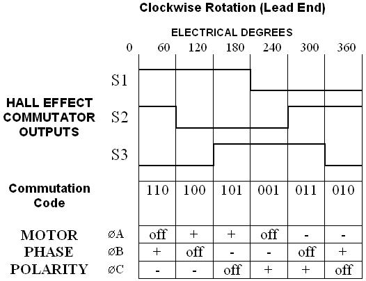
Synchronous Motors The HURST® permanent magnet synchronous motors are reversible permanent-split capacitor motors identical in construction to the HURST® stepping motors. In operation the permanent magnet rotor poles lock-in with the effectively rotating stator field and the motor runs at synchronous speed. The 60 Hz can-stack motors operate at synchronous speeds of 300 and 600 RPM. High quality gearing is available for the can-stack motors. The ceramic rotor magnet material provides a relatively high flux resulting in a good torque to size ratio at moderate cost. In addition the permanent magnet construction provides inherent dynamic braking and low rotor speed for quiet operation and rapid acceleration. The disadvantages of permanent magnet motors are a limited ability to accelerate inertial loads and high sensitivity to the parameters of voltage and phasing capacitor. The first of these problems may be minimized by gearing or in some cases flexible couplings. The sensitivity to voltage and phasing capacitor directly affects the directional reliability of both starting and running under load. In HURST® motor designs directional reliability is a primary consideration and is assured when motors are operated with the recommended capacitor within a voltage range of ±10% of nominal. Variable Frequency Operation of AC Motors Sometimes a single motor is specified for both 50 and 60 Hz operation. Since inductive reactance and capacitive reactance vary dissimilarly with frequency, optimum performance must usually be compromised when a single winding/capacitor combination is operated at different frequencies. Some types of motors are more sensitive than others to frequency changes. The factory should be consulted before 50/60Hz operation of a motor is planned. Operation over a wider frequency range is extremely difficult to accomplish with capacitor phased motors and is not recommended. Reliable operation requires a two phase power supply with applied voltage a function of frequency. Applying 50Hz to Synchronous Motor Designs Permanent magnet synchronous motors designed for optimum performance at 60Hz will be directionally un-reliable when operated at 50Hz. Rated torque will be 20% to 25% lower at 50Hz. Additionally, the output speed will be 5/6 the speed while applying 50Hz to the motor. By increasing the capacitor value of the recommended capacitor by 30%, 50Hz may be applied to 60Hz motors without sacrificing reliability. 50Hz torque will be approximately 5% less than rated 60Hz torque. Why Capacitor Start AC Synchronous Motors? All Permanent Magnet AC Synchronous motors manufactured at Hurst are of the capacitor start variation. These motors, which are classified in the sub-fractional group, find various applications in situations requiring frequent and prolonged starting periods. As the name suggests, these motors run at synchronous speed. The speed of a single phase AC synchronous motor can be determined using the formula Synchronous speed (in RPM) = 120f/p where f is the frequency of the power supply and p is the number of poles. For the same starting torque, the capacitor motor when compared to the split-phase motor requires half of the current for starting. The auxiliary winding of the capacitor motor has twice the number of turns of the split-phase AC motor. A split-phase AC motor basically has an inductive auxiliary winding. The lesser current in the auxiliary winding of the capacitor motor results in less copper loss and subsequently less heat generated by that motor. Because of the capacitor in the winding, the capacitor motor has the advantage of a greater phase shift between the current of the stator winding and that of the auxiliary winding. Phase shift is typically about 80% compared to 20% for the split-phase motor. The increased phase shift translates into easier starting for the capacitor start motor. Starting & Stopping Characteristics Virtually instant starting and stopping characteristics are among the principal advantages of an AC Synchronous motor. Generally, the motor will start within 1 ½ cycles of the applied frequency and will stop within 5 mechanical degrees. The motor will start and reach it full synchronous speed within 5 to 25 milliseconds. The unusually short stopping distance of an AC Synchronous motor is obtained by simply de-energizing the motor. No mechanical or electrical braking is necessary. The quick stopping is the result of the slow rotor speed and the presence of a no-load reluctance torque produced by the permanent magnet and the tooth construction of the stator and rotor. Stepper Motor Series Hurst offers a broad line of permanent magnet stepping motors of the economical can-stack construction type with step angles in the range of 7.5 to 18 degrees. A complete line of high quality gearing is available for several of the models. Stepping is achieved by electronic commutation of the stator windings. Each pulse input to the commutation circuitry produces a fixed angular increment of rotation of the output shaft. The error in this increment is non-cumulative and is typically less than ±5% of the nominal step angle value. Up to a maximum pulse rate known as the pull-in rate, a stepping motor maintains an error free ratio rotational position to input pulses with the ability to start, stop or reverse direction. Above this rate, the motor must be accelerated and decelerated to maintain pulse to step integrity. Because of the precise incremental motion characteristics, stepping motors are well suited to positioning applications of all types. The permanent magnet rotor also provides inherent detent torque when the stator is not energized. The performance of a stepping motor in a given application is highly dependent upon its control circuitry. Stepping Motor Construction and Operation 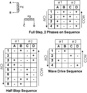 “Can-stack” stepping motors consist of two stacked sets of toothed stator poles, circular coils and a cylindrical
ceramic permanent magnet rotor with radial alternating north and south poles. The number of rotor poles is equal to
the number of stator teeth in each set of poles. When the stator pole coils are energized, the rotor will align
itself between the two equal stator fields. Typically the number of poles are such that the motors have step angles
in the range of 7.5 to 20 degrees.
“Can-stack” stepping motors consist of two stacked sets of toothed stator poles, circular coils and a cylindrical
ceramic permanent magnet rotor with radial alternating north and south poles. The number of rotor poles is equal to
the number of stator teeth in each set of poles. When the stator pole coils are energized, the rotor will align
itself between the two equal stator fields. Typically the number of poles are such that the motors have step angles
in the range of 7.5 to 20 degrees.
A single step of the rotor corresponds to a change of magnetic polarity for one set of stator teeth. This change in polarity is brought about by reversing the direction of current flow in the coil associated with those teeth. The rotor motion for a single step with no load applied is that of a damped oscillation. The dampening characteristics are modified by frictional and inertial loading, the sequence in which windings are energized, and the electronic dampening in the drive circuitry. Stepping Motors Step Angle Accuracy 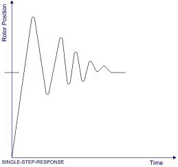 The average value of the measured step angles of an unloaded stepping motor over 360˚ will be equal to the nominal
step angle. The maximum deviation of the individual steps from the nominal step angle is the error usually specified
as a non-cumulative or incremental step angle error. The typical maximum value for this error in a can-stack motor
with two phases energized is ±5%.
The average value of the measured step angles of an unloaded stepping motor over 360˚ will be equal to the nominal
step angle. The maximum deviation of the individual steps from the nominal step angle is the error usually specified
as a non-cumulative or incremental step angle error. The typical maximum value for this error in a can-stack motor
with two phases energized is ±5%.
Stepping Motor Stepping Sequences For continuous rotation a repeating sequence of changing tooth polarity is required. Differences in motor performance characteristics result from different sequences. A commonly used scheme for stepping is to energize both stator coils and to reverse the current in alternate coils with each successive step. This results in a four step sequence. Reversing the sequence reverses the direction of rotation. This is called a full step mode with two phases on. It is also possible to step the rotor with the same angular increment by energizing only one phase each step. This is also a four step sequence and is known as a wave drive. Since only half the copper volume is being used, the efficiency is lower and there is less damping with this scheme than with two phases on. A third sequence alternates between one and two phases energized to produce ½ the step angle of the previous sequences. The half step sequence requires eight steps. Angular resolution is improved and the smaller step angle provides an improvement in damping. However, it should also be noted that this scheme produces alternate “weak” steps when only one phase is energized. Stepping Motor Resonance 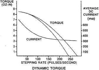 All stepping motors exhibit resonance at certain pulse rates. In typical can-stack stepping motor applications resonances
are most commonly encountered at low frequencies (less than 100 pulses per second). Although there is no loss of steps at
these frequencies, there is an increase in vibration and noise. This becomes even more noticeable when a gear train is
coupled to the motor. When operation at resonant frequencies cannot be avoided, some improvement in damping may be obtained
with increased frictional damping, reduced input power, modified drive circuitry or half-stepping.
All stepping motors exhibit resonance at certain pulse rates. In typical can-stack stepping motor applications resonances
are most commonly encountered at low frequencies (less than 100 pulses per second). Although there is no loss of steps at
these frequencies, there is an increase in vibration and noise. This becomes even more noticeable when a gear train is
coupled to the motor. When operation at resonant frequencies cannot be avoided, some improvement in damping may be obtained
with increased frictional damping, reduced input power, modified drive circuitry or half-stepping.
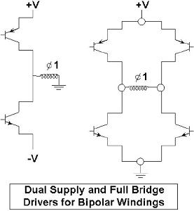
Stepping Motor Torque Characteristics The maximum torque developed by the motor is the static or holding torque. It is measured while displacing the rotor one step with one or two phases energized. During continuous stepping with a constant voltage supply the dynamic torque developed decreases with increasing stepping rate. This reflects the relatively large inductance to resistance ratio of the motor. In a typical dynamic torque curve (commonly called an L/R curve) the lower curve represents the maximum torque load which the motor will start and stop without losing steps (pull-in). The upper curve represents the maximum torque which the motor can develop at a given pulse rate or alternately, the maximum rate to which a given load can be accelerated (pull-out). Motor torque at high pulse rates can be increased by increasing the input to the motor using a variety of drive techniques. These include simple schemes such as increasing the voltage directly or decreasing the time constant by adding external series resistance, and more elaborate techniques such as bi-level voltage drives in which winding current is controlled. When overdriving techniques are used to extend motor performance, consideration must be given to the maximum permissible temperature rise of the motor winding based on the insulation rating of the motor. Stepping Motor Bifilar and Bipolar Operation 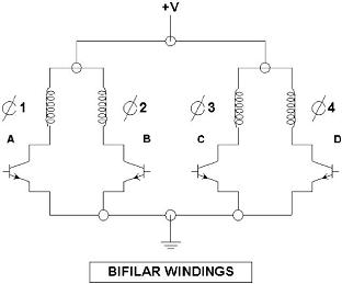 The terms bifilar and bipolar refer to two different types of windings that may be used in the stator coils.
Bipolar windings contain a single coil in each stator half. The switching circuitry used to reverse the direction
of current flow with this coil is typically of the full bridge or dual supply type. Bifilar windings contain two
coils in each stator half. When they are connected as shown in the figure, the magnetic polarity of the stator teeth
can be reversed by switching from one coil to the other of each pair with a unipolar supply. Note that although a
bifilar-wound motor does contain four coils or “phases,” it is operated as a two phase motor. Bifilar-wound PM
steppers are widely used because of the drive circuit simplicity. All stock HURST® stepping motors use this winding
configuration.
The terms bifilar and bipolar refer to two different types of windings that may be used in the stator coils.
Bipolar windings contain a single coil in each stator half. The switching circuitry used to reverse the direction
of current flow with this coil is typically of the full bridge or dual supply type. Bifilar windings contain two
coils in each stator half. When they are connected as shown in the figure, the magnetic polarity of the stator teeth
can be reversed by switching from one coil to the other of each pair with a unipolar supply. Note that although a
bifilar-wound motor does contain four coils or “phases,” it is operated as a two phase motor. Bifilar-wound PM
steppers are widely used because of the drive circuit simplicity. All stock HURST® stepping motors use this winding
configuration.
 Bifilar and bipolar-wound motors do exhibit some performance differences. Since the winding volume per phase of a
bifilar-wound stepper is only half that of a bipolar-wound stepper, the attainable ampere-turns for a given input
power will not necessarily be lower for the bifilar-wound motor. Therefore, the torque is lower. However, with an
L/R drive the bipolar coil with its larger volume will have a larger time constant. At high stepping rates the
bipolar-wound motor’s torque will decrease to approximately the same level as that of the bifilar-wound motor.
Bifilar and bipolar-wound motors do exhibit some performance differences. Since the winding volume per phase of a
bifilar-wound stepper is only half that of a bipolar-wound stepper, the attainable ampere-turns for a given input
power will not necessarily be lower for the bifilar-wound motor. Therefore, the torque is lower. However, with an
L/R drive the bipolar coil with its larger volume will have a larger time constant. At high stepping rates the
bipolar-wound motor’s torque will decrease to approximately the same level as that of the bifilar-wound motor.
The choice of winding type will depend upon the application. The holding torque for a bipolar version of a given motor will be 20-30% higher than the bifilar version. Dynamic torque differences will depend upon the drive circuitry. With the simplest drive circuits the bipolar performance exceeds the bifilar only at low frequencies. As drive circuit complexity increases the bipolar performance becomes superior. Hybrid Stepper Motor The term, hybrid, is due to the motor being operated under the combined principles of permanent magnet and variable reluctance. The most popular step angle for the hybrid stepping motor is 1.8 degrees, or 200 steps per revolution. The Hybrid Stepper is the motor solution for precision movements or higher speed applications in factory and office automation. Hybrid Stepping Motor Mechanical Construction The construction of a hybrid stepper motor is characterized by having a coil, multi-toothed stator and rotor poles with a permanent magnet. This construction offers small step angle, sufficient torque and speed. A 200 step per revolution (1.8˚) step motor with 2 phases “on” (4 phase instant) has 50 rotor teeth on each rotor yoke. These are referred to as poles. The stator has 8 poles. A phase state in a motor with permanent magnets is considered a single polarity current or voltage. A cycle is considered a positive and negative current or voltage. These motors are usually wound with a bifilar winding, this makes it possible to drive a motor from a single polarity voltage without using reversing switches or transistors to reverse the current to the motor windings. Each of the poles has 2 windings and is mistakenly called a 4 phase motor because of this. If the motor is driven from a bipolar drive or ac power source only 1 winder per pole is required. Advantages of Hybrid Stepper Motor
The DC power supply is switched to each phase in sequence to operate a stepping motor. Ordinary DC or AC power supplies will not run a stepping motor unless the driving circuit includes a switching circuit. The signal circuit is used to generate pulses, change or stop frequencies and to generate reversing signals. The logic circuit distributes signal pulses to each wire according to the number of phases and the excitation method. Stepper Drives Unipolar Drives Motor phase winding current is switched in only one direction (typically to ground).
Motor phase winding current is switched in both directions.
Full/Half Stepping Steps the motor by alternating phase windings in fully on or fully off mode
Gradually energizes a phase to create smaller subdivisions of each full-step
|
||||||||||||||||||||||||||||||||||||||||||||||||||||||||||||||||||||||||||||||||||||||||||||||||||||||||||||||||||||||||||||||||||||||||||||||