Brushless DC (BLDC) Motor Family
NT DYNAMO® Brushless DC (BLDC) Geared Specifications:
| Spur |
Click to Enlarge |
Up to 600:1 Gear Ratio
Up to 200 oz-in [1412 mN-m] of Torque
AGMA 7 Gear Quality
|
| |
|
| Planetary |
|

Click to Enlarge |
Wide Selection of Gear Ratios and Features
Inline, Right Angle, and Metric
High Torque and Low Backlash
|
| |
|
| Some factors to consider in maximizing your
application system’s performance: |
| |
|
- Torque Multiplication
- Radial Loading
- Noise
|
- Speed Reduction
- Axial Loading
- Inertia Matching
|
Spur
gearheads will suit most needs in relatively low-torque
applications. However, spur configurations have higher
backlash and are usually less efficient than planetary types
of similar construction. For constant velocity and
unidirectional applications where backlash is less of a
concern, spur gearheads are ideal.
Planetary
gearheads are generally specified for their high rated
torque and high input speed. Planetary gearheads are more
robust with higher accuracy, lower backlash, and longer life
than spur gearheads. They are well suited for higher load
applications in small packages ranging from nut runners and
nut setters to small medical tools, pumps, and other
devices.
The gearhead solution (Spur Vs. Planetary)
is primarily dependent upon the application. Some factors to
be considered in making proper trade-offs between cost and
performance are shown below.
|
|
DESIGN FACTORS
|
GEARHEAD TYPE
|
|
SPUR
|
PLANETARY
|
|
Torque Capacity
|
Lower
|
Higher |
|
Power to Weight Ratio |
Lower |
Higher |
|
Power to Size Ratio |
Lower |
Higher |
|
Torsional Stiffness |
Lower |
Higher |
| Backlash |
Higher |
Lower |
|
Available Number of Gear Ratios |
Higher |
Lower |
|
Operating Speed |
Lower |
Higher |
| Size |
Larger |
Smaller |
| Cost |
Lower |
Higher |
|
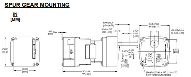
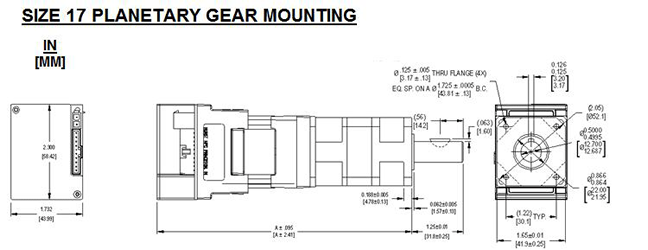
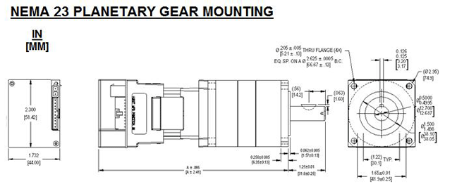
NT DYNAMO® Brushless DC (BLDC) Geared Diagrams:
|
|
Model
|
Overall Length (A) in [mm]
|
|
0
|
4.87 [123.7]
|
|
6
|
7.12 [180.8]
|
|
|
|
Model
|
Overall Length (A) in [mm]
|
|
Model
|
Overall Length (A) in [mm]
|
|
0
|
6.49 [164.8]
|
4
|
8.74 [222.0]
|
|
0*
|
6.98 [177.3]
|
4*
|
9.23 [234.4]
|
|
* Gear Reductions 16:1 and higher
|
|
|
|
Model
|
Overall Length (A) in [mm]
|
|
Model
|
Overall Length (A) in [mm]
|
|
0
|
6.68 [169.7]
|
4
|
8.93 [226.8]
|
|
0*
|
7.50 [190.5]
|
4*
|
9.75 [247.7]
|
|
* Gear Reductions 16:1 and higher |
|
NT DYNAMO® Brushless DC (BLDC) Geared Part Number Specification:
Spur Gearing Part Number Identification Matrix
| Rated Speed |
Rated Torque @ 24Vdc |
Rated Current @ 24Vdc |
Gear Ratio |
Gear Stages |
Max. Radial Load |
Max. Axial Load |
Wt. |
Length “A” inches [mm] |
Part Number |
| RPM |
(oz.in.) |
(Amps) |
|
|
(lb) |
(lb) |
(lb) |
ValuDrive® Control |
Model # |
Winding |
Gear # |
| 93 to 280 |
15 |
0.35 |
2:1 |
2 |
7 |
5 |
1.6 |
4.87 [123.7] |
0 |
E |
G00 |
| 75 |
1.4 |
2.9 |
7.12 [180.8] |
6 |
E |
G00 |
| 37 to 112 |
38 |
0.35 |
5:1 |
2 |
7 |
5 |
1.6 |
4.87 [123.7] |
0 |
E |
G01 |
| 188 |
1.4 |
2.9 |
7.12 [180.8] |
6 |
E |
G01 |
| 18 to 56 |
75 |
0.35 |
10:1 |
2 |
7 |
5 |
1.6 |
4.87 [123.7] |
0 |
E |
G02 |
| 2001 |
1.4 |
2.9 |
7.12 [180.8] |
6 |
E |
G02 |
| 6.2 to 18 |
2001 |
0.35 |
30:1 |
3 |
7 |
5 |
1.6 |
4.87 [123.7] |
0 |
E |
G03 |
| 3.1 to 9.3 |
2001 |
0.35 |
60:1 |
3 |
7 |
5 |
1.6 |
4.87 [123.7] |
0 |
E |
G04 |
| 1.8 to 5.6 |
2001 |
0.35 |
100:1 |
4 |
7 |
5 |
1.6 |
4.87 [123.7] |
0 |
E |
G05 |
| 0.6 to 1.8 |
2001 |
0.35 |
300:1 |
5 |
7 |
5 |
1.6 |
4.87 [123.7] |
0 |
E |
G06 |
| 0.3 to 0.9 |
2001 |
0.35 |
600:1 |
5 |
7 |
5 |
1.6 |
4.87 [123.7] |
0 |
E |
G07 |
1Motor rated torque will exceed the 200 oz.in. [1412 mN-m] maximum geartrain rating.
If this service is anticipated, a current limiting device should be used.
- All values are at nominal rated input voltage.
- Ambient operating temperature range: 0 to 40°C.
- At 25°C ambient the max motor winding operating temperature rise is 65°C with gearmotor mounted to a
4" x 4" x 0.25" aluminum plate.
- Performance data shown is typical. More detailed data is available from Hurst for each of the above ratings.
- Refer to the Customer Data Sheet supplied with your system or contact Hurst for other gear ratios and voltages (7 to 45 Vdc).
|
|
Planetary Gearing Part Number Identification Matrix
|
Rated Speed |
Rated Torque @ 24Vdc |
Rated Current @ 24Vdc |
Gear Ratio |
Gear Stage |
Gear Head Inertia |
Gear Head Backlash (Std./Low) |
Wt. |
Length “A” inches [mm] |
Part Number |
|
RPM |
lb.in. |
Amps |
|
|
oz.in.-sec2 |
arc-min |
lb. |
ValuDrive® Control |
Model # |
Winding |
Gear # |
Size
17 |
225 to 675 |
1.7 |
1 |
3:1 |
Single |
3.83E-04 |
6/3 |
2.1 |
6.49 [164.8] |
2 |
C |
P10 |
| 6.8 |
3.6 |
3:1 |
Single |
3.83E-04 |
6/3 |
3.4 |
8.74 [222.0] |
4 |
C |
P10 |
| 168 to 506 |
2.3 |
1 |
4:1 |
Single |
2.41E-04 |
6/3 |
2.1 |
6.49 [164.8] |
2 |
C |
P11 |
| 9 |
3.6 |
4:1 |
Single |
2.41E-04 |
6/3 |
3.4 |
8.74 [222.0] |
4 |
C |
P11 |
| 122 to 368 |
3.1 |
1 |
5.5:1 |
Single |
1.76E-04 |
6/3 |
2.1 |
6.49 [164.8] |
2 |
C |
P12 |
| 12 |
3.6 |
5.5:1 |
Single |
1.76E-04 |
6/3 |
3.4 |
8.74 [222.0] |
4 |
C |
P12 |
| 96 to 289 |
3.9 |
1 |
7:1 |
Single |
1.51E-04 |
6/3 |
2.1 |
6.49 [164.8] |
2 |
C |
P13 |
| 16 |
3.6 |
7:1 |
Single |
1.51E-04 |
6/3 |
3.4 |
8.74 [222.0] |
4 |
C |
P13 |
| 67 to 202 |
5.6 |
1 |
10:1 |
Single |
1.54E-04 |
6/3 |
2.1 |
6.49 [164.8] |
2 |
C |
P14 |
| 23 |
3.6 |
10:1 |
Single |
1.54E-04 |
6/3 |
3.4 |
8.74 [222.0] |
4 |
C |
P14 |
| 42 to 127 |
8.5 |
1 |
16:1 |
Double |
2.22E-04 |
10/5 |
2.7 |
6.98 [177.3] |
2 |
C |
P15 |
| 34 |
3.6 |
16:1 |
Double |
2.22E-04 |
10/5 |
4 |
9.23 [234.4] |
4 |
C |
P15 |
| 31 to 92 |
12 |
1 |
22:1 |
Double |
1.73E-04 |
10/5 |
2.7 |
6.98 [177.3] |
2 |
C |
P16 |
| 47 |
3.6 |
22:1 |
Double |
1.73E-04 |
10/5 |
4 |
9.23 [234.4] |
4 |
C |
P16 |
| 24 to 72 |
15 |
1 |
28:1 |
Double |
1.50E-04 |
10/5 |
2.7 |
6.98 [177.3] |
2 |
C |
P17 |
| 60 |
3.6 |
28:1 |
Double |
1.50E-04 |
10/5 |
4 |
9.23 [234.4] |
4 |
C |
P17 |
| 17 to 51 |
21 |
1 |
40:1 |
Double |
1.32E-04 |
10/5 |
2.7 |
6.98 [177.3] |
2 |
C |
P18 |
| 85 |
3.6 |
40:1 |
Double |
1.32E-04 |
10/5 |
4 |
9.23 [234.4] |
4 |
C |
P18 |
| 12 to 37 |
29 |
1 |
55:1 |
Double |
1.31E-04 |
10/5 |
2.7 |
6.98 [177.3] |
2 |
C |
P1A |
| 1171 |
3.6 |
55:1 |
Double |
1.31E-04 |
10/5 |
4 |
9.23 [234.4] |
4 |
C |
P1A |
| 10 to 29 |
37 |
1 |
70:1 |
Double |
1.30E-04 |
10/5 |
2.7 |
6.98 [177.3] |
2 |
C |
P1B |
| 1491 |
3.6 |
70:1 |
Double |
1.30E-04 |
10/5 |
4 |
9.23 [234.4] |
4 |
C |
P1B |
| 6.7 to 20 |
521 |
1 |
100:1 |
Double |
1.30E-04 |
10/5 |
2.7 |
6.98 [177.3] |
2 |
C |
P1C |
|
NEMA
23 |
225 to 675 |
1.7 |
1 |
3:1 |
Single |
1.68E-03 |
6/3 |
3.2 |
6.68 [169.7] |
2 |
C |
P20 |
| 6.8 |
3.6 |
3:1 |
Single |
1.68E-03 |
6/3 |
4.5 |
8.93 [226.8] |
4 |
C |
P20 |
| 168 to 506 |
2.3 |
1 |
4:1 |
Single |
1.27E-03 |
6/3 |
3.2 |
6.68 [169.7] |
2 |
C |
P21 |
| 9 |
3.6 |
4:1 |
Single |
1.27E-03 |
6/3 |
4.5 |
8.93 [226.8] |
4 |
C |
P21 |
| 122 to 368 |
3.1 |
1 |
5.5:1 |
Single |
1.08E-03 |
6/3 |
3.2 |
6.68 [169.7] |
2 |
C |
P22 |
| 12 |
3.6 |
5.5:1 |
Single |
1.08E-03 |
6/3 |
4.5 |
8.93 [226.8] |
4 |
C |
P22 |
| 96 to 289 |
3.9 |
1 |
7:1 |
Single |
1.01E-03 |
6/3 |
3.2 |
6.68 [169.7] |
2 |
C |
P23 |
| 16 |
3.6 |
7:1 |
Single |
1.01E-03 |
6/3 |
4.5 |
8.93 [226.8] |
4 |
C |
P23 |
| 67 to 202 |
5.6 |
1 |
10:1 |
Single |
9.50E-04 |
6/3 |
3.2 |
6.68 [169.7] |
2 |
C |
P24 |
| 23 |
3.6 |
10:1 |
Single |
9.50E-04 |
6/3 |
4.5 |
8.93 [226.8] |
4 |
C |
P24 |
| 42 to 127 |
8.5 |
1 |
16:1 |
Double |
1.28E-03 |
10/5 |
4.2 |
7.50 [190.5] |
2 |
C |
P25 |
| 34 |
3.6 |
16:1 |
Double |
1.28E-03 |
10/5 |
5.5 |
9.75 [247.7] |
4 |
C |
P25 |
| 31 to 92 |
12 |
1 |
22:1 |
Double |
1.09E-03 |
10/5 |
4.2 |
7.50 [190.5] |
2 |
C |
P26 |
| 47 |
3.6 |
22:1 |
Double |
1.09E-03 |
10/5 |
5.5 |
9.75 [247.7] |
4 |
C |
P26 |
| 24 to 72 |
15 |
1 |
28:1 |
Double |
1.01E-03 |
10/5 |
4.2 |
7.50 [190.5] |
2 |
C |
P27 |
| 60 |
3.6 |
28:1 |
Double |
1.01E-03 |
10/5 |
5.5 |
9.75 [247.7] |
4 |
C |
P27 |
| 17 to 51 |
21 |
1 |
40:1 |
Double |
9.53E-04 |
10/5 |
4.2 |
7.50 [190.5] |
2 |
C |
P28 |
| 85 |
3.6 |
40:1 |
Double |
9.53E-04 |
10/5 |
5.5 |
9.75 [247.7] |
4 |
C |
P28 |
| 12 to 37 |
29 |
1 |
55:1 |
Double |
9.51E-04 |
10/5 |
4.2 |
7.50 [190.5] |
2 |
C |
P2A |
| 1171 |
3.6 |
55:1 |
Double |
9.51E-04 |
10/5 |
5.5 |
9.75 [247.7] |
4 |
C |
P2A |
| 10 to 29 |
37 |
1 |
70:1 |
Double |
9.50E-04 |
10/5 |
4.2 |
7.50 [190.5] |
2 |
C |
P2B |
| 1491 |
3.6 |
70:1 |
Double |
9.50E-04 |
10/5 |
5.5 |
9.75 [247.7] |
4 |
C |
P2B |
| 6.7 to 20 |
521 |
1 |
100:1 |
Double |
9.49E-04 |
10/5 |
4.2 |
7.50 [190.5] |
2 |
C |
P2C |
1Motor rated torque can exceed indicated maximum gearhead rating. If this service is anticipated, a current limiting
device should be used.
- All values are at nominal rated input voltage.
- Ambient operating temperature range: 0 to 40°C.
- At 25°C ambient the max motor winding operating temperature rise is 65°C with gearmotor mounted to a
4" x 4" x 0.25" aluminum plate.
- Performance data shown is typical. More detailed data is available from Hurst for each of the above ratings.
- Refer to the Customer Data Sheet supplied with your system or contact Hurst for other gear ratios and voltages (7 to 45 Vdc).
|
|
Dynamo Part Number Identification Matrix
|
|
Product Family
|
Operating Mode
|
Control Method (Input Signal)
|
Encoder (ppr)
|
Thermal Protection
|
Model -
Rated Torque (oz-inch)
|
Input Voltage (Vdc)
|
Winding (See Chart)
|
Mechanical Features
|
Preset Speed10 (RPM)
|
|
DM - Dynamo
|
A – External1
|
0 – None
|
0 - None
|
0 - None
|
0 – See Note 11
|
012 – 12 V
|
A
|
100 - Size 17 without cables
|
0 - None
|
|
|
B - Open Loop Speed
|
1 – Analog3
|
1 - 100 ppr
|
|
1 - 5
|
024 – 24 V
|
B
|
101 - Size 17 with cables
|
1 - Special13
|
|
|
C - Closed Loop Speed
|
2 – Analog4(w/ 5Vdc supply)
|
2 - 250 ppr
|
|
2 - 10
|
036 – 36 V
|
C
|
200 - NEMA 23 without cables
|
A – 250
|
|
|
D – Preset Speed2
|
3 – PWM3,5
|
3 - 400 ppr
|
|
3 - 20
|
045 – 45 V
|
D
|
201 - NEMA 23 with cables
|
B – 300
|
|
|
E – Torque12 (Open Loop)
|
4 – PWM5
(w/ 5Vdc supply)
|
4 - 1000 ppr
|
|
4 - 30
|
048 – 48 V
|
E
|
G00-079 Spur Gear Ratios with cables
|
C – 500
|
|
|
|
5 – PWM & Direction3,6
|
5 - 256 ppr (w/index)7
|
|
5 - 40
|
|
|
P10-P1C9 Planetary Gear Ratios (Size 17) with cables
|
D – 600
|
|
|
|
6 - PWM & Direction6
(w/ 5Vdc supply)
|
|
|
6 - See Note11
|
|
|
P20-P2C9 Planetary Gear Ratios (NEMA 23) with cables
|
E – 750
|
|
|
|
7 - ON / OFF3
|
|
|
|
|
|
|
F – 900
|
|
|
|
8 ON / OFF4
|
|
|
|
|
|
|
G – 1000
|
|
|
|
|
|
|
|
|
|
|
H – 1200
|
|
|
|
|
|
|
|
|
|
|
J – 1500
|
|
|
|
|
|
|
|
|
|
|
K – 1800
|
|
|
|
|
|
|
|
|
|
|
L - 2000
|
|
|
|
|
|
|
|
|
|
|
M – 2500
|
|
|
|
|
|
|
|
|
|
|
N – 3000
|
|
|
|
|
|
|
|
|
|
|
P – 3500
|
|
|
|
|
|
|
|
|
|
|
Q – 3600
|
|
|
|
|
|
|
|
|
|
|
R – 4000
|
|
|
|
|
|
|
|
|
|
|
S - 4500
|
1Only Motor phase and commutation signal outputs are supplied. (User supplies their own motor drive).
2Use only with Control Method
7 – ON/OFF
or8 – ON/OFF.
3
User to supply 5 Vdc control logic signal; Power supply able to supply a typical current of 35 mA.
4
Internally supplied 5 Vdc source; max current = 5 mA.
5
PWM input signal used in conjunction with direction line (Pin 7).
6
PWM input signal (Pin 3) used as command and direction.
7
Only available with Operating Mode A– External.
8
Use only with Operating Mode A – External or 45 Vdc for all other
operating modes.
9
See Dynamo Spur Gearing part number Identification Matrix or Dynamo Planetary Gearing part number Identification Matrix for
Gear Options.
10
Use only with Operating Mode D - Preset Speed.
Preset Speed must be below solid portion of the diagonal line of the winding curve
selected. The
maximum continuous torque is dependent upon the preset speed selected. Other Preset speeds available upon
request.
11
Use only with Spur and Planetary Gearing; See Dynamo Spur Gearing part number Identification Matrix
or Dynamo Planetary Gearing
part number Identification Matrix for Gear Options.
12
Use only with 1 – Analog
or 2 – Analog (w/ 5Vdc supply).
13
If standard listed speeds do not meet your needs, contact the factory for your specific requests.
|
|
Motor Only Curves
 |
NT DYNAMO
® Brushless DC (BLDC) Geared Model Table:
(Note: For Features Or Speeds Not Listed In Table, Contact Factory)
|
DMA0100024EG030 |
Spur |
200 |
1412.3 |
30 |
Feedback |
See diagram |
100 line |
24 |
.1 |
.35 |
6.2 to 18 |
28 |
20.3 |
27.2 |
771 |
Contact
Factory
|
DMA0100024EG040 |
Spur |
200 |
1412.3 |
60 |
Feedback |
See diagram |
100 line |
24 |
.1 |
.35 |
3.1 to 9.3 |
28 |
20.3 |
27.2 |
771 |
Contact
Factory |
DMA0100024EG050 |
Spur |
200 |
1412.3 |
100 |
Feedback |
See diagram |
100 line |
24 |
.1 |
.35 |
1.8 to 5.6 |
28 |
20.3 |
27.2 |
771 |
Contact
Factory |
DMA0106024EG000 |
Spur |
75 |
529.6 |
2 |
Feedback |
See diagram |
100 line |
24 |
.2 |
1.4 |
93 to 280 |
4 |
4.1 |
27.2 |
771 |
Contact
Factory |
DMA0106024EG010 |
Spur |
188 |
1327.6 |
5 |
Feedback |
See diagram |
100 line |
24 |
.2 |
1.4 |
37 to 112 |
4 |
4.1 |
27.2 |
771 |
Contact
Factory |
DMA0106024EG020 |
Spur |
200 |
1412.3 |
10 |
Feedback |
See diagram |
100 line |
24 |
.2 |
1.4 |
18 to 56 |
4 |
4.1 |
27.2 |
771 |
Contact
Factory |
DMA0104024CP100 |
Planetary |
108.8 |
768.3 |
3 |
Feedback |
Size 17 |
100 line |
24 |
.6 |
3.6 |
225 to 675 |
.83 |
1.02 |
27.2 |
771 |
Contact
Factory |
DMA0104024CP120 |
Planetary |
192 |
1355.8 |
5.5 |
Feedback |
Size 17 |
100 line |
24 |
.6 |
3.6 |
122 to 368 |
.83 |
1.02 |
27.2 |
771 |
Contact
Factory |
DMA0104024CP140 |
Planetary |
368 |
2598.7 |
10 |
Feedback |
Size 17 |
100 line |
24 |
.6 |
3.6 |
67 to 202 |
.83 |
1.02 |
27.2 |
771 |
Contact
Factory |
DMA0104024CP200 |
Planetary |
108.8 |
768.3 |
3 |
Feedback |
NEMA 23 |
100 line |
24 |
.6 |
3.6 |
225 to 675 |
.83 |
1.02 |
35.2 |
998 |
Contact
Factory |
DMA0104024CP220 |
Planetary |
192 |
1355.8 |
5.5 |
Feedback |
NEMA 23 |
100 line |
24 |
.6 |
3.6 |
122 to 368 |
.83 |
1.02 |
35.2 |
998 |
Contact
Factory |
DMA0104024CP240 |
Planetary |
368 |
2598.7 |
10 |
Feedback |
NEMA 23 |
100 line |
24 |
.6 |
3.6 |
67 to 202 |
.83 |
1.02 |
35.2 |
998 |
|
DMB1100024EG030 |
Spur |
200 |
1412.3 |
30 |
Analog Open |
See diagram |
100 line |
24 |
.1 |
.35 |
6.2 to 18 |
28 |
20.3 |
27.2 |
771 |
Contact
Factory |
DMB1100024EG040 |
Spur |
200 |
1412.3 |
60 |
Analog Open |
See diagram |
100 line |
24 |
.1 |
.35 |
3.1 to 9.3 |
28 |
20.3 |
27.2 |
771 |
Contact
Factory |
DMB1100024EG050 |
Spur |
200 |
1412.3 |
100 |
Analog Open |
See diagram |
100 line |
24 |
.1 |
.35 |
1.8 to 5.6 |
28 |
20.3 |
27.2 |
771 |
Contact
Factory |
DMB1106024EG000 |
Spur |
75 |
529.6 |
2 |
Analog Open |
See diagram |
100 line |
24 |
.2 |
1.4 |
93 to 280 |
4 |
4.1 |
27.2 |
771 |
Contact
Factory |
DMB1106024EG010 |
Spur |
188 |
1327.6 |
5 |
Analog Open |
See diagram |
100 line |
24 |
.2 |
1.4 |
37 to 112 |
4 |
4.1 |
27.2 |
771 |
Contact
Factory |
DMB1106024EG020 |
Spur |
200 |
1412.3 |
10 |
Analog Open |
See diagram |
100 line |
24 |
.2 |
1.4 |
18 to 56 |
4 |
4.1 |
27.2 |
771 |
Contact
Factory |
DMB1104042CP100 |
Planetary |
108.8 |
768.3 |
3 |
Analog Open |
Size 17 |
100 line |
24 |
.6 |
3.6 |
225 to 675 |
.83 |
1.02 |
27.2 |
771 |
Contact
Factory |
DMB1104024CP120 |
Planetary |
192 |
1355.8 |
5.5 |
Analog Open |
Size 17 |
100 line |
24 |
.6 |
3.6 |
122 to 368 |
.83 |
1.02 |
27.2 |
771 |
Contact
Factory |
DMB1104024CP140 |
Planetary |
368 |
2598.7 |
10 |
Analog Open |
Size 17 |
100 line |
24 |
.6 |
3.6 |
67 to 202 |
.83 |
1.02 |
27.2 |
771 |
Contact
Factory |
DMB1104024CP200 |
Planetary |
108.8 |
768.3 |
3 |
Analog Open |
NEMA 23 |
100 line |
24 |
.6 |
3.6 |
225 to 675 |
.83 |
1.02 |
35.2 |
998 |
Contact
Factory |
DMB1104024CP220 |
Planetary |
192 |
1355.8 |
5.5 |
Analog Open |
NEMA 23 |
100 line |
24 |
.6 |
3.6 |
122 to 368 |
.83 |
1.02 |
35.2 |
998 |
Contact
Factory |
DMB1104024CP240 |
Planetary |
368 |
2598.7 |
10 |
Analog Open |
NEMA 23 |
100 line |
24 |
.6 |
3.6 |
67 to 202 |
.83 |
1.02 |
35.2 |
998 |
|
|
DMB2106024EG010 |
Spur |
188 |
1327.6 |
5 |
Analog Open |
See diagram |
100 line |
24 |
.2 |
1.4 |
37 to 112 |
4 |
4.1 |
27.2 |
771 |
Contact
Factory |
DMC2000024EG000 |
Spur |
15 |
105.9 |
2 |
Analog Closed |
See diagram |
None |
24 |
.1 |
.35 |
93 to 280 |
28 |
20.3 |
27.2 |
771 |